


This is an XML gauge for the default Lear Jet 45 - Flight Simulator 2004
- Introduction -
Hello everyone, I'm changing the gauges in the default Lear 45 to XML format. The gauge that
I'm currently working on is the Attitude Backup gauge. All bitmaps used here were extracted
from Lear_45.gau using the latest version of FS Panel Studio. The image editing and convertion to bitmap format was done using PSP. Also,
the bitmaps were then converted to 8-bit images using ImageTool which is found in the Microsoft ® gmax Gamepack SDK.
- Primary Flight Display -
Now, before I go any further, I need to determine if the default PFD (Primary Flight
Display) Attitude Indicator gauge is acurate. What I mean is, when I set the Autopilot
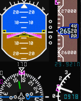
to climb at 1000 fpm (indicated as 0978 fpm in Figure 1.1), at 271 KIAS to FL330, the PFD Attitude Indicator
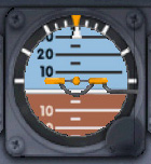
shows that I'm climbing at approximately 1 or 2 degrees, and the Backup
Attitude Indicator shows that I'm climbing at approximately 5 or 6
degrees (see Figure 1.2). Note that I'm passing FL265 for FL330 and the Altimeter
is set correctly at 29.92 The Backup Attitude Indicator is using the new XML coding that
is listed here. For the moment I'm going to assume that the Autopilot, as well as the PFD Attitude
Indicator, are fully functional in the Lear 45.
Question?
How do I determine the precise Scale ratio?
My source(s) of information concerning this gauge are from the most excellent tutorials at FS2x.com and particularly the PDF document found in the Tutorials.
Chapter 1: Main Body Sections
NOTE: If this Web page doesn't render correctly it's because this Web site is optimized for FireFox! Internet Explorer users Please click here to view XML code.
Please send results/comments to:raptor@kgz.shawbiz.ca
- The <Scale Y=" "/> Ratio -
^Top
I need help with determining the Precise <Scale Y=" "/> ratio
in the default Lear 45 Backup Attitude gauge. The entire code for this XML gauge can be viewed here, but the area I'm having trouble with is from Chapter 1: Main Body Sections PDF document. The Quote is as follows:
<Shift>

						    <Value Minimum="-90" Maximum="90">(A:Attitude indicator pitch degrees, degrees) /-/</Value>

						    <Scale Y="4"/>

						</Shift>
"Here we see a value line that generates a number in the range of -90 to +90.
Notice the <Scale Y="4"/> instruction. Without this, the bitmap
controlled would move the number of pixels being generated by the value line, from a datum
position. This is fairly restrictive, so to give it total flexibility, the scale
instruction is used. The Y character tells the bitmap to move in the Y
direction (up and down). This could be an X character and produce sideway movement.
The Y="4" multiplies the value generated by 4. So if the
positive maximum of 90 is generated, the bitmap will move 4x90=360 pixels."
I posted a message on the forums at http://www.forums.flightsim.com for some help with this question. Thanks to Flight Sim Panel & Gauges Forum Moderator - Bill aka n4gix for his quick response to my quest! Quote from the Flight Sim Forum as follows:
Determining the scalar factor is simple...
Measure (in Photoshop) the number of pixels for the range.
Divide this number by the variable's range.
260 pixels for 0 to 300 variable range
260/300 = .86666 scaling factor
540 pixels for a 100 to 1500 variable range
540/(1500-100) = .3857142
The Backup Attitude Number Strip aka Ladder shown in Figure 1.3, was extracted from the Lear_45.cab using FS Panel Studio. The bitmap size is 100 pixels by 354 pixels as shown
in the following XML code (Click here to see full XML code):
<Image Name="attitude_bu_ladder.bmp" ImageSizes="100,354">
I have two variable ranges to choose from:
0to300100to1500
The Variable range for an Attitude Indicator is 90 (uses equal values for both positive
(+90) and negative (-90) values), which falls into the 0 to 300
variable range. The measurement on the bitmap from +90 to -90 using Photoshop, in
pixels, is 218 (286-68=218). Using the 0 to 300 variable
range, the precise scalar for this bitmap is:
218/180 = 1.21111(218/2)/(180/2) = 1.21111
- or simply -109/90 = 1.21111
Thank-you Bill! The updated XML code can be viewed here, and this also leads to several new questions concering this particular gauge.
Personal Note: When I first looked at the Chapter 1: Main Body Sections PDF document I may have misunderstood what was actually
being stated. What I mean is, when you look at the example the document provides:
<Value Minimum="-90" Maximum="90">(A:Attitude indicator pitch degrees, degrees) /-/</Value>
and continue reading till you see "the bitmap will move 4x90=360 pixels.", I first
noticed the 4 x 90 = 360 and not the pixels part of the
statement. My error was that I was thinking 360 degrees (because of the degrees, degrees
in the code I had degrees in my train of thought), not 360 pixels. A little confusing for example
figures to use, but that's what happened (I think) .. lol
Question? The new scalar of 1.21111 is a repeating number. How many
digits should I enter, following the decimal, for the new XML <Scale Y="1.21111"/>
scalar, or any other repeating value(s) that I may find in other gauges?
Question? Are there any other Variable Ranges for calculating the scalar factor?
Another timely response from Bill! His answers to these questions are as follows:
For FS gauge purposes, two decimal precision is sufficient, thus Scale Y="1.21"
should be adequate.
The only time you need be concerned about "ranges" in any guage is if the scale used is non-linear.
A good example might be an airspeed tape, where the segment from 0 to 100 is
say, 235 px, but the segment from 100 to 300 is 180 px.
The reason for the non-linearity is that at lower speeds greater precision is required...
In such a case, you would divide the movement into two sections of code, using the appropriate scalar for each section, e.g.:
0 - 100 = 2.35 px/knot
100 - 300 = 1.11 px/knot
//TODO: Find example two or three section "number strip bitmap" to use for Figure 1.4
//Please kontact me for ideas & suggestions at://raptor@kgz.shawbiz.ca
- Final XML Lear45!Backup Attitude -
^Top
<Gauge Name="Backup Attitude" Version="1.0" Author="KGZ">
<!-- Kopyright (C) 2003-06 Kritical GamerZ -->
<Image Name="attitude_bu_background.bmp" Luminous="No" UseTransparency="Yes" ImageSizes="104,104"/>
<Element>
<!-- Failures -->
<Failures>
<FAIL_GAUGE_ATTITUDE Action="0"/>
</Failures>
</Element>
<Element>
<MaskImage Name="attitude_bu_mask.bmp" UseTransparency="Yes" ImageSizes="104,104">
<Axis X="52" Y="52"/>
</MaskImage>
<Image Name="attitude_bu_ladder.bmp" ImageSizes="100,354">
<Axis X="50" Y="177"/>
</Image>
<Shift>
<Value Minimum="-90" Maximum="90">(A:Attitude indicator pitch degrees, degrees) /-/</Value>
<Scale Y="1.21"/>
</Shift>
<Rotate>
<Value>(A:Attitude indicator bank degrees, radians)</Value>
</Rotate>
</Element>
<Element>
<!-- Heading Bug -->
<Position X="52" Y="52"/>
<Image Name="attitude_bu_heading_bug.bmp" UseTransparency="Yes" ImageSizes="104,104">
<Axis X="52" Y="52"/>
</Image>
<Rotate>
<Value>(A:Attitude indicator bank degrees, radians)</Value>
</Rotate>
</Element>
<Element>
<!-- Bars -->
<Position X="22" Y="39"/>
<Image Name="attitude_bu_bars.bmp" UseTransparency="Yes" ImageSizes="82,30"/>
</Element>
</Gauge>
- What's Next? -
^Top
This part of the tutorial focused on one specific bitmap, the attitude_bu_ladder.bmp,
from the Backup Attitude gauge in the default Lear 45. The more observant XML gauge designer my
have noticed something odd about the final XML code. Why do I have Luminous="No"? Go to Part II in the gauge tutorials to see the answer!
